Axial Fan Blade Angle

The flow is axial at entry and exit.
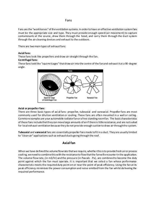
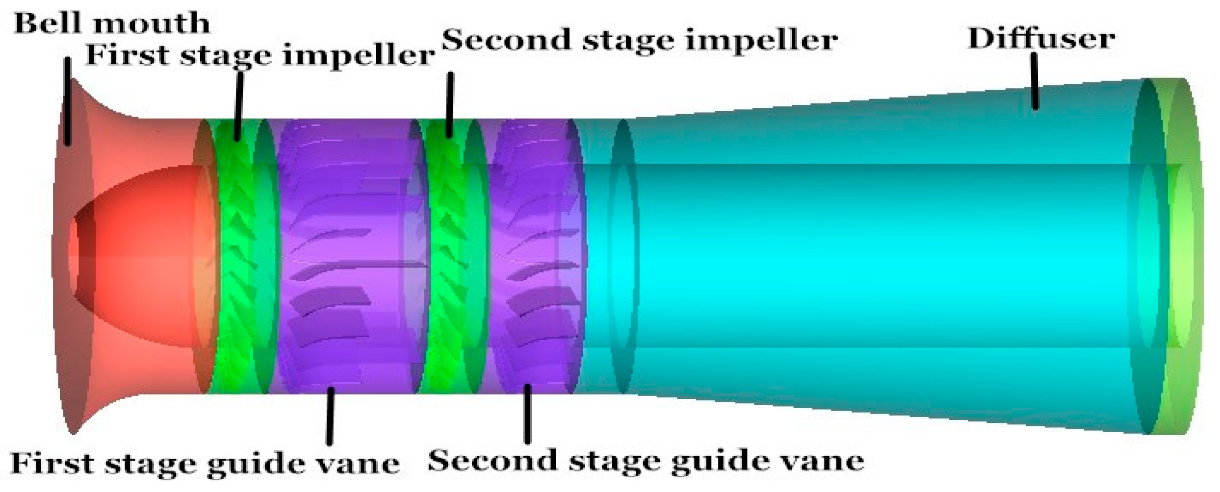
Axial fan blade angle. The fan is designed to produce a pressure difference and hence force to cause a flow through the fan factors which determine the performance of the fan include the number and shape of the blades. These fans include an internal mechanism that can automatically adjust blade angle while the fan rotor is in motion. The characteristics for a typical fan are given in fig. It is worth noting that in these cases some important and critical items include.
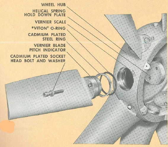
The blade pitch control is applied to the axial fan with a fixed speed to control the air flow. Industrial fan blades axial fan blades or propellers. The pitch angle of the blades are varied through a controller e g a pneumatic actuator with increasing blade angle for increasing flow rates and vice versa for reducing flow rates. The number of blades.
Axial fans can have widely varied operating characteristics depending on blade width and shape number of blades and tip speed. The results show that the flow patterns are drastically sensitive to the variation of the blade angle of attack and the fan performances are closely related to the inter blade flow behaviors. The blade pitch angle. There are typically four criteria used in the design of propeller blades or fan blades.
Hudson fans all rotate clockwise looking into the airflow. The inlet and outlet velocities of the air through the blades will be the same for axial fans and different for centrifugal fans v ᵢ and v ₒ. The inter blade flows of three axial flow fans with different blade angles of attack are subsequently studied using this method. The shape of your blades and the direction they travel will define the performance characteristics of your fan.
Due to their compact design and high efficiency most of the variable pitch axial flow fans find applications in the thermal power stations where fresh air is needed forced draft or process involving high temperatures such as. The blade angle is adjusted with the help of a hydraulic actuator fixed with the shaft from minimum to maximum position to ensure maximum possible efficiency. For blower wheels centrifugal wheels see blower wheels page. Fig 3 shows the velocity diagram for the air flowing into the fan inlet and out of it outlet.
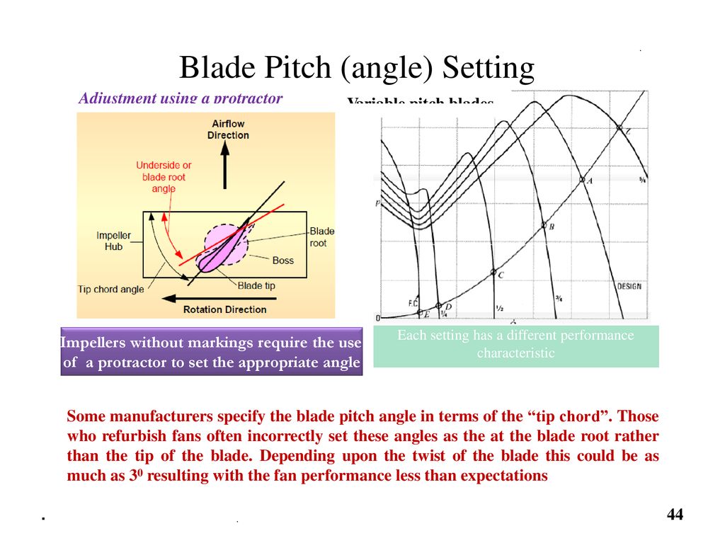
Pitch angle blade tip angle below the horizontal required to do the design work and move air upward.


